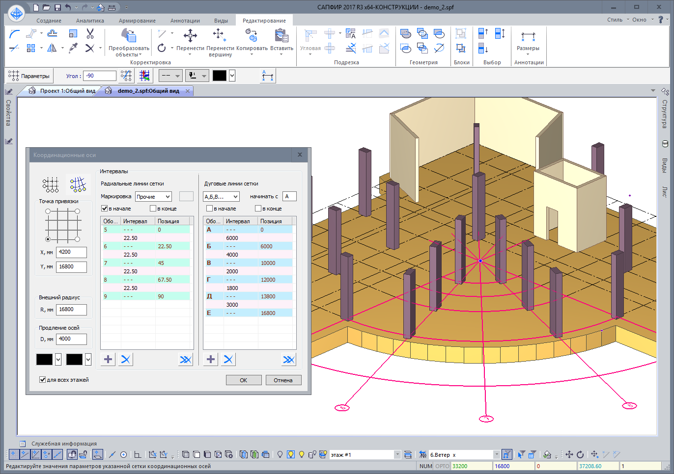
Rectangular and radial grid lines are projected on the plan and in 3D on any projection, including perspective images..
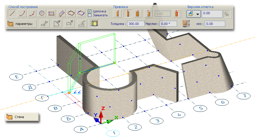
Walls and partitions of different shape, including multi-layer materials. The wall height may be modified dynamically when the floor height is changed. In the meshed model, the walls may be presented as plates (load bearing walls) or as loads (partitions, thermal insulation layers, etc.)
Slabs may be generated with previously created or imported line or its fragment. It is possible to specify zones of different thickness in the slab or to simulate capitals above columns. When the meshed model is generated, such zones are shifted from the main plate by offsets of a specified length.

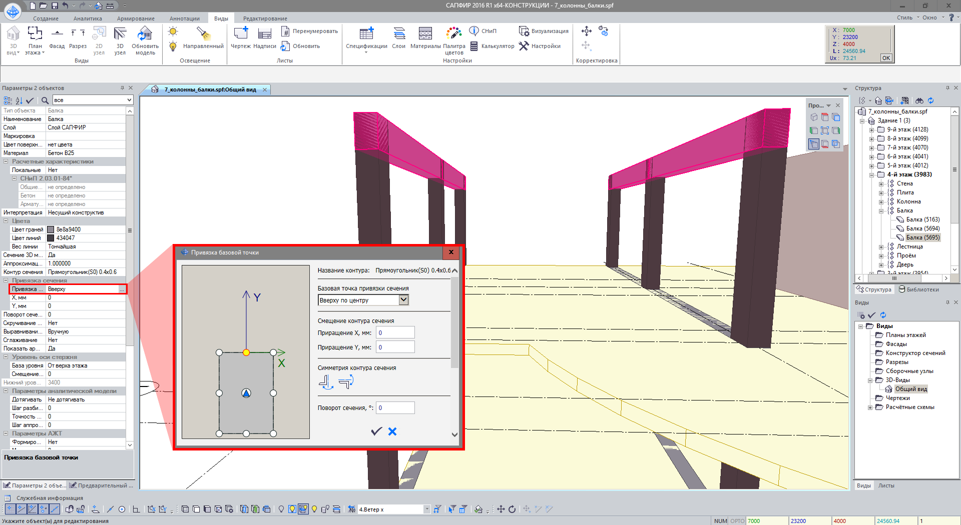
Columns and beams match cross-sections with the RC and metal profiles in LIRA-FEM program. Punching shear contours are generated automatically for columns with account of the slab edge and the presence of closely spaced openings. Perfectly rigid bodies are generated automatically in beams and columns; so it is possible to simulate the real behaviour of the structure.
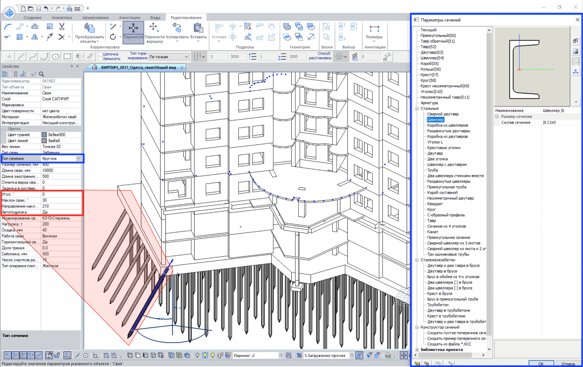
Piles are vertical bars of a certain cross-section and are defined as an array or single pile. Their stiffness is presented in terms of bearing capacity and settlement.

Joints for panel buildings are modelled parametrically and may be vertical with account of embedded items as well as platform or contact joints. The stiffness of platform and contact joints is computed depending on the thickness and material of mortar joint, and the thickness of the objects included in the joint.
Support options (rigid, hinged with eccentricity or free edge) are modelled at places where components are connected. Elements with support options are exported to VISOR-SAPR module with appropriate modifications: joints are 'thrown apart', perfectly rigid bodies are created, groups with coupled DOF are created, etc.
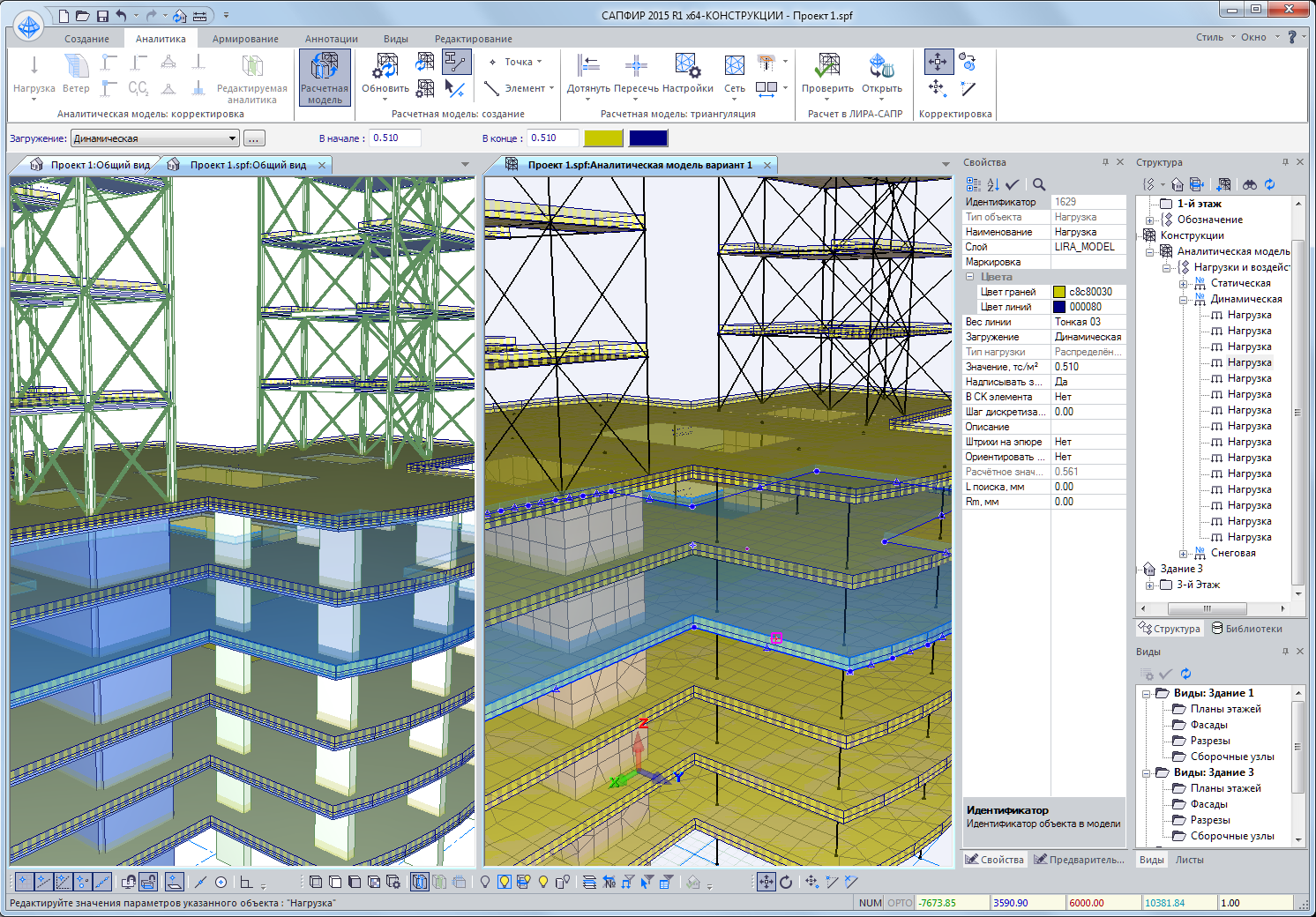
A set of tools to assign loads: concentrated loads, linear and surface loads, moving loads on span, wind and earthquake loads. To all loads it is possible to assign load type, duration factor, safety factors, sign variability, groups of integrated load cases / mutual exclusion / accompanying. Based on the input data, load combinations are generated automatically (DCF and DCL tables).
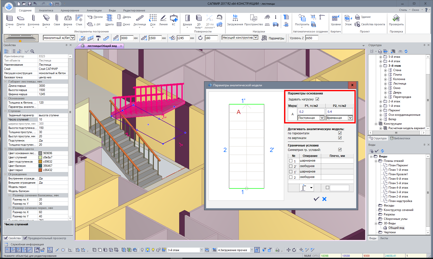
Stairs are generated automatically: both the physical and analytical model. Reinforced concrete staircases are modelled with plates, while staircases of cut stringers and closed stringers are modelled with bars of specified cross-section. The bearing elements of a staircase may be assigned dead and live load as well as support options at places where these elements intersect the building frame.
The room defines a zone with an arbitrary name and generates loads in the analytical model. The areas, volumes and notations are shown on the floor plan.
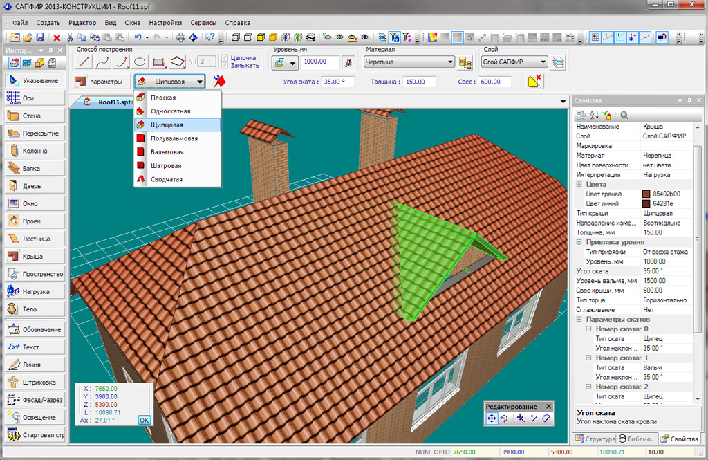
Several roof types may be generated dynamically: hip roof, half-hip roof, flat roof, shed roof, gable roof, helm roof or vaulted roof with account of pitch, overhang, structural thickness, snap level. Wall models can be trimmed up to roof pitches.

With 3D bodies and surfaces it is possible to generate the frame of a building. Storeys of a specified height and floor slabs are automatically generated. Columns are created at the intersection of grid lines. The surface may be included in the meshed model as a system of bars or shells.
Notations may be displayed on plan, facade, section and 3D.

The material and texture libraries contain not only the physical and mechanical properties of materials, but also the necessary design parameters and structural requirements for further analysis of reinforcement in VISOR-SAPR module.
Lists of all components and bills of materials are automatically generated as tables, placed on drawing sheets and exported to CSV files. It is also possible to obtain approximate cost of materials and export physical quantities to a DBF file for estimators.
Models may be exported in IFC, XML, DXF, POV, 3DS formats. Architectural projects may be imported from IFC files as well as DWG, DXF files.
When the drawings are used as floor plan DXF underlays, it is possible to generate 3D object automatically. The program will automatically recognise cross-sections of piles, columns and beams, wall and slab thicknesses, the size of openings specified in the DXF file. Models may be imported from STL, 3DS, OBJ, MESH, MSH files. Option to compare versions of the project